-
-
-
-
Quality and Specifications
-
-
-
Specifications & Declarations
Specification and Test Methods for Optical Filters
All optical filters are tested according to industry standards for optical components. AHF analysentechnik relies on the definitions and test methods as described in the standard ISO 10110 of the International Organization for Standardization (ISO), as well as in the ANSI/OEOSC OP1.002-2009 standard of the American National Standards Institute (ANSI). Verification of the quality standard is done both at our suppliers and randomly per lot at AHF.
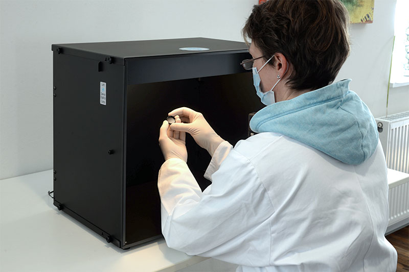
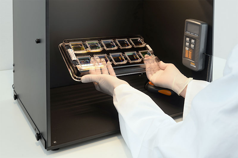
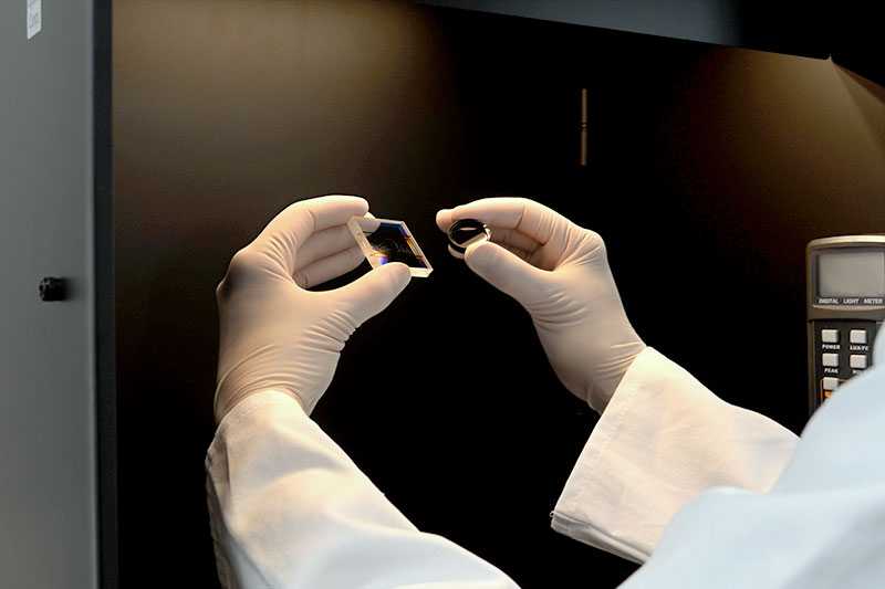
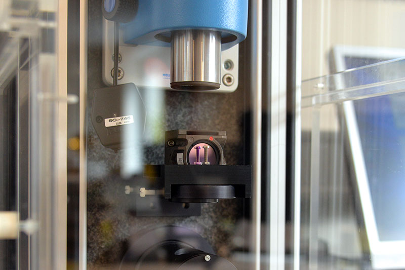
As defined in the standards, the materials to be tested are illuminated with either a 40-watt incandescent lamp or two 15-watt fluorescent lamps against a black background. AHF uses a standards-compliant test station specifically designed for ANSI-compliant visibility testing. Reference standards and a stereo microscope are available for tests according to the ISO standard. Each filter is tested by eye and compared to a reference standard with respect to scratch/dig specifications (see standard ISO-10110-7:2017: Surface imperfections). According to these definitions, visual imperfections are assessed such as scratches and holes on the surface, including imperfections such as chipping at the edges and corners, and mechanical imperfections. Of course, this is done by trained personnel.
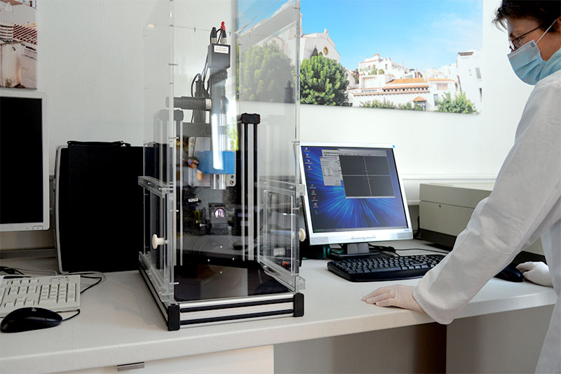
The flatness of the beam splitters can be checked with a Shack-Hartmann wavefront sensor, the beam deflection (plane parallelism of the filter surfaces) by means of an autocollimator.
The Standard Specifications of Our Filters and Beam Splitters:
| Standard Specification | Requirements |
| Clear Aperture (CA): |
≥ 80% to ≥ 90% Please note: CA beam splitter is elliptical defined. CA can be smaller for very small filters. |
| Surface Flatness: | not specified, if not listed otherwise |
| Surface Flatness (Wedge): | ≤ 5 to ≤ 20 angular seconds @633nm |
| Chamfer (Bevel): | none, or up to ≤ 0,3 mm @45°, must be specified |
| Edge Chipping: | ≤ 0,5 mm for beam splitter |
| Corner Chamfers: | none, unless otherwise specified |
| Substrate used: | nBK7, Borofloat, Fused Silica or LCD |
| Scratch / Dig: | 60–40 |
| Mechanical Length Tolerances: | +/- 0,1 mm, if not listed otherwise |
| Mechanical thickness tolerances: | +/- 0,05 mm, if not listed otherwise |
Annotations
Clear Aperture (CA): Depending on the manufacturer, a clear aperture of ≥ 80% or ≥ 90% of the surface is guaranteed. Please note that for beam splitters with AOI 45°, it's defined elliptically.
Surface Flatness: Depending on the application area of the optical component, a higher surface flatness requirement may be necessary here. Therefore, please discuss your requirements with us in advance!
Surface Parallelism / Wedge: The plane parallelism of the surfaces is very good in most cases and is rarely a decisive criterion.
Chamfer / Bevel: The desired bevel should always be specified. This may be useful or necessary if the coating of the optical component is to be specially protected at the edge.
Edge Chipping: Cutting the components may result in small chipping of the coating at the cut edges. Whereby it is crucial here that the guaranteed free aperture is maintained.
Scratch / Dig: The manufacturer's specification for surface defects in terms of scratches and holes (digs) refers here to the ANSI standard. The value given as the scratch value corresponds to the brightness of the scratches compared to the reference. Scratches are thus characterized by their width, and the customer defines a requirement in this range by specifying the maximum width for a scratch to be within the clear opening (CA) of the filter. Thus, a "60" scratch designation specifies 60 µm as the maximum allowable width of a scratch that is within the free aperture of the filter. The sum of the length of all scratches must not exceed ¼ of the free aperture of the filter.
Holes (digs) are characterized by their actual diameters, which are specified in units of 10 µm. A requirement in this range can be characterized by the customer by specifying the maximum diameter of a hole within the free aperture (CA) of the filter.
Specifically, a "40" dig designation specifies 400 µm (0.4 mm) as the maximum allowable width of a hole that may be in the free aperture of the filter. If there are multiple extinguishers, further restrictions apply. This is also based on a comparison measurement to the reference.
Some of the standard specifications can be intensified quite easily if there are higher requirements (e.g. higher flatness of beam splitters), but for some its not that simple. Therefore, please contact us to check the specifications you require!
REACH/RoHS Declarations
We can provide you with the following declaration for products of the Spectral Analysis & Photonics product range:
- REACH/RoHS Declaration (PDF)


